Dynamic Effects

Fragmentation of weapon casings

The MARS fragmentation algorithm for solids inserts discrete cracks within a hexahedral mesh treating failure at the structural level rather than in the material constitutive equations. The initial mesh is subdivided into clusters of elements. Cracks may form between clusters when a local measure of damage exceeds a local allowable. Cracks can propagate and/or coalesce forming fragments of various shapes and sizes. The parameters of the algorithm have been calibrated for specific weapons so that generated fragment distributions match arena test data.
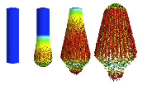
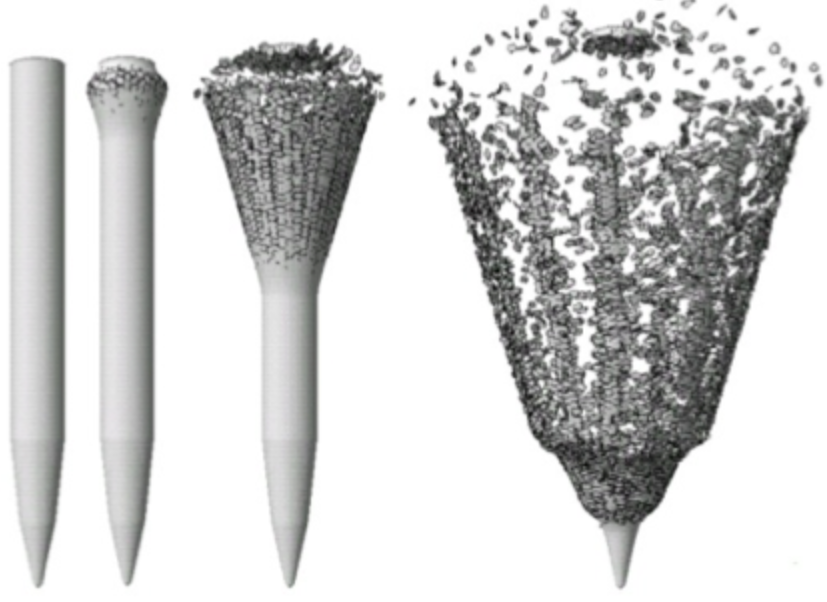
Fragmentation of IED device.
The MARS fragmentation algorithm inserts small microcracks in the mesh which coalesce into larger cracks and the eventual breakup of the weapon casing.

Blast induced fragmentation

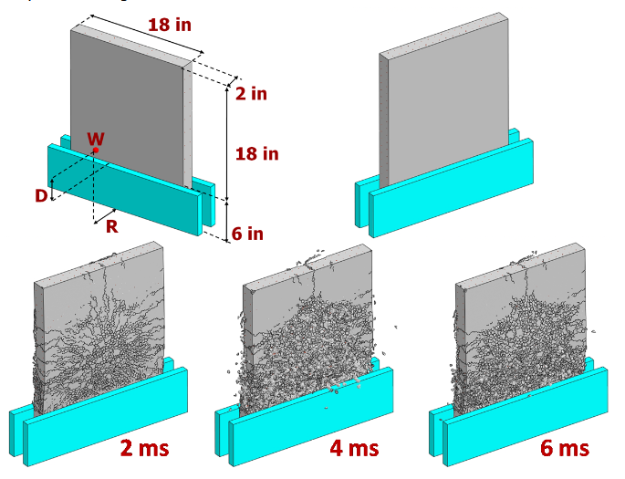
The simulation of damage induced by a blast on a reinforced concrete wall is reported in this figure. The top of the figure shows the geometry of the wall as well as the position of the charge. The bottom of the figures reports the damage evolution at three time instants during the simulation. At the beginning the wall shows a failure that resembles the effect of a concentrate load with several radial cracks emanating for the center of the wall. Later damage concentrates at the bottom (where the wall is clamped) and the final failure mode is characterized by the complete shearing of the wall base.

Impact induced fragmentation

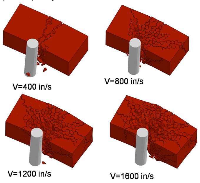
This simulation consists of a metallic rod impacting a quasi-brittle brick at various velocities. The objective of this study is to demonstrate the ability of the Lattice Discrete Particle Model to simulate impact induced fragmentation. The image shows the failure patterns associated with four different velocities, ranging from 400 in/s to 1600 in/s. For the lowest velocity (top left), the brick splits essentially in two fragments. At 800 in/s (top right), there are four major fragments with some debris in between. At higher velocities (bottom left and right) the number of fragments increases up to the complete fragmentation of the brick.
Projectile penetration
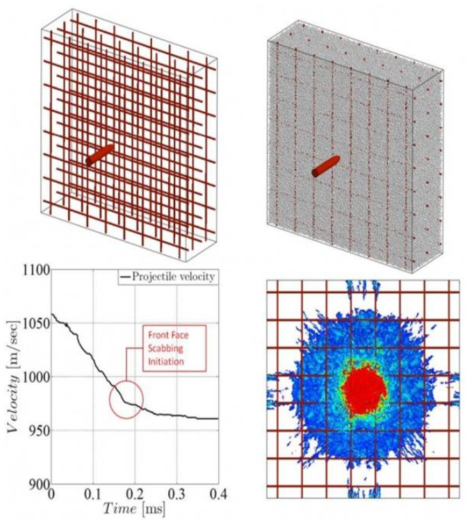
This figure shows the simulation of a steel projectile penetration through a reinforced concrete slab. Concrete, rebars, and projectile are modeled by LDPM, elasto-platic beam elements, and elasto-plastic brick elements, respectively (top left and top right). The striking velocity is 1060 m/s. The the projectile velocity history during the penetration is reported in the bottom left of the figure. Initially, the projectile velocity decreases linearly with time. About 0.18 ms after the impact the front face scabbing initiates and the projectile deceleration is greatly reduced. After 0.35 ms the projectile achieved complete penetration with an exit velocity of about 960 m/s. The damage distribution after the penetration event is shown in the bottom right of the figure.

Advancing Aerospace Technologies for More Than 20 Years